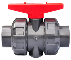
UPVC Ball Valves True Union Ball Valve
The ball is made with precision turning and grinding to ensure that its true roundness and smoothness is achieved. This provides for lower torqe requirement and ease of handling. True union design provides for tight shut-off. These valves are most suited for water treatment and chlorination applications. The Socket and Screwed Joint Available.
ADVANTAGES:
- NSF listed and materials meet drinking water standard
- Smooth opening and closing thanks to a lower torque
- 100% pure virgin material, CaCO3 free (Chalk)
- UV resistant powder added
- 100% pressure testing before leaving the factory
- Can be assembled with Pneumatic/Electtric Actuators
- Material: PVC, CPVC, Clear PVC, PP, PVDF
- Size: 1/2'' - 4''; 20mm - 110mm; DN15 - DN100
- Standard: ANSI, DIN, JIS, CNS
- Joint End: Socket, Threaded(NPT, PT, BSPF), Fusion, Welding
- Seat - PTFE, TPV ; ORING - EPDM, VITON
- Working Pressure: 150 PSI
- Operating Temperature: PVC(0~55℃); CPVC and PP(0~95℃)
- Working Pressure: 150 PSI
- Handle color : red, blue, green,
orange
Valve body color : PVC(dark gray), CPVC(light gray), PP(light yellow) Clear PVC(transperance), PVDF(ivory)
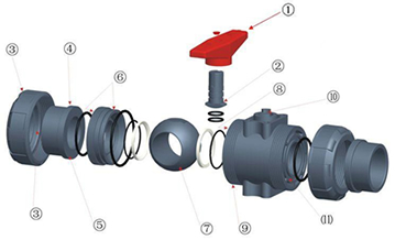
DESCRIPTION:
SPECIFICATIONS:
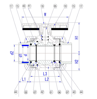
| ITEM | PART | MATERIAL | QTY |
| 01 | BODY | PVC / CPVC / PP / CLEAR PVC / PVDF | 1 |
| 05 | STEM | PVC / CPVC / PP / CLEAR PVC / PVDF | 1 |
| 06 | BALL | PVC / CPVC / PP / CLEAR PVC / PVDF | 1 |
| 07 | SEAT | TPV / PTFE | 2 |
| 08 | SEAL CARRIER |
PVC / CPVC / PP / CLEAR PVC / PVDF | 1 |
| 10 | HANDLE |
ABS | 1 |
| 15 | UNION NUT |
PVC / CPVC / PP / CLEAR PVC / PVDF | 2 |
| 17 | UNION END |
PVC / CPVC / PP / CLEAR PVC / PVDF | 2 |
| 18 | CAP | ABS | 1 |
| 41 | ORING | EPDM / VITON | 2 |
| 42 | ORING | EPDM / VITON | 1 |
| 43 | ORING | EPDM / VITON | 2 |
| 44 | ORING | EPDM / VITON | 2 |
|
||||||||||||||||||||||||||||||||||||||||||||||||||||||||||||||||||||||||||||||||||||||||||||||||||||||||||||||||||||||
|
||||||||||||||||||||||||||||||||||||||||||||||||||||||||||||||||||||||||||||||||||||||||||||||||||||||||||||||||||||||||||||||||||||||||||||||||
DESIGNS:
- Underside handle extends the length so that both OFF block will not be exposed, more beautiful
- Extrusive circular plane change to both side plane, easy processing and assemble
- Lateral plane and ribs of the Union Cap, from the right-angle change to incline to increase the intensity
- Union end from right-angle to slope increase in a round protruding rib to increase the intensity
- Surface of Oring change to a plane, and each have been cutting lathe in order to ensure its flatness
- Seal carrier and Oring slot is processed by machine, sealing performance is improved
- Each ball has increased turning and grinding to ensure that its true roundness and smoothness. So much easier to handle and not easy leak
- Inside body is processed via CNC machine to make sure acurate dimensions
- Increase the slope of trapezoidal teeth and the number of teeth in order to ensure their connection strength
- Through hole is processed via CNC machine to make sure the stability of sealing
- Slot dimension is improved, sealing performance is strengthened.
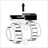
DISASSEMBLY DETAILS :
 A
A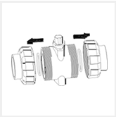 B
B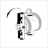 C
C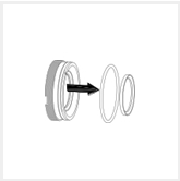 C1
C1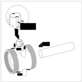 D
D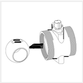 E
E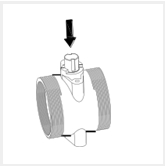 F
F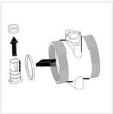 G
G
- A - Pull Out The Handle
- B - Take Apart The Nuts
- C - Turn The Seal Carrier In An Anticlockwise Direction
- C1 - Take Out The Seat and Oring
- D - Push The Ball
- E - Pick Out The Ball
- F - Press The Shaft
- G - Pick Out The Seat and Oring
Note :
- For abvoe "D" step, pls take note the groove position "1" on the shaft
- To assemble the valve, pls follow up the steps from "G" to "A"


Follow us on :